Detailed Introduction:
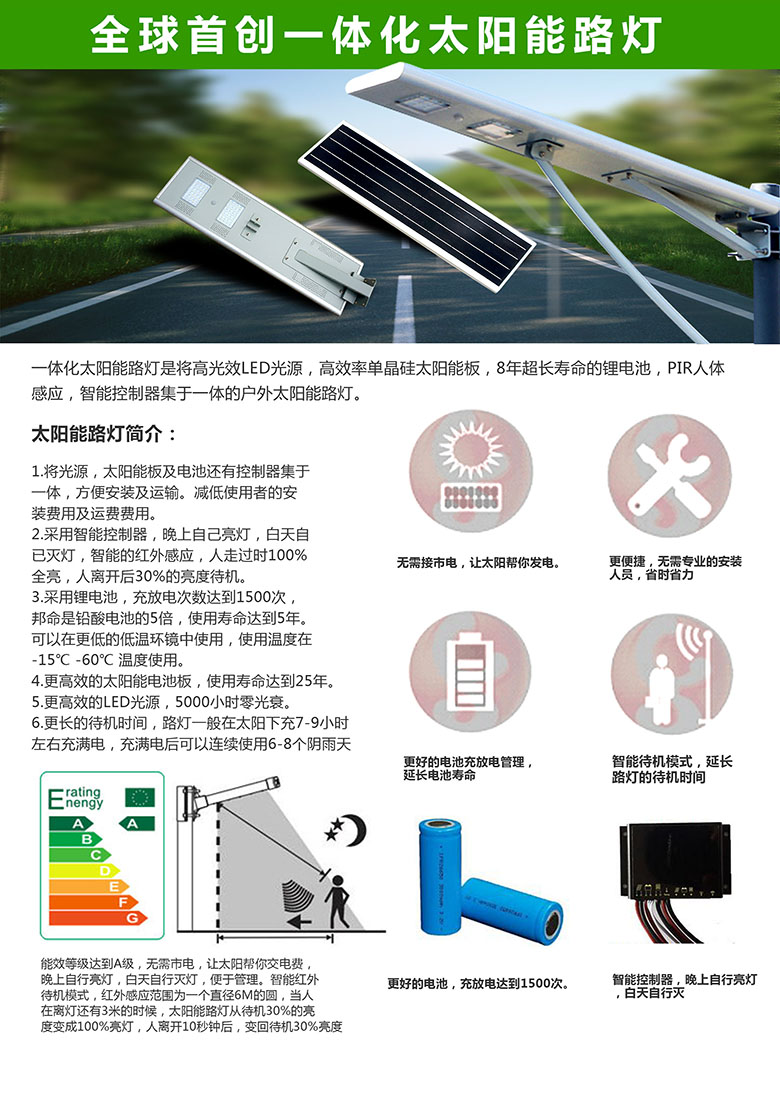
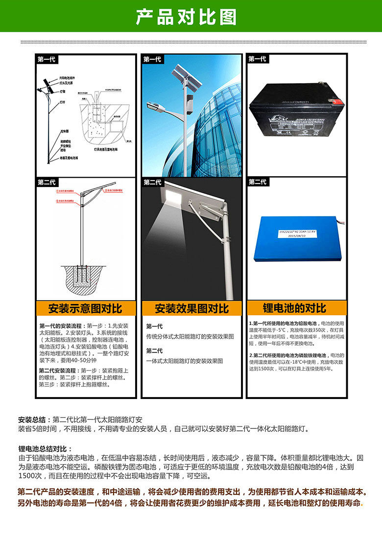
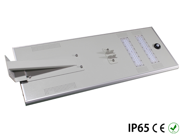
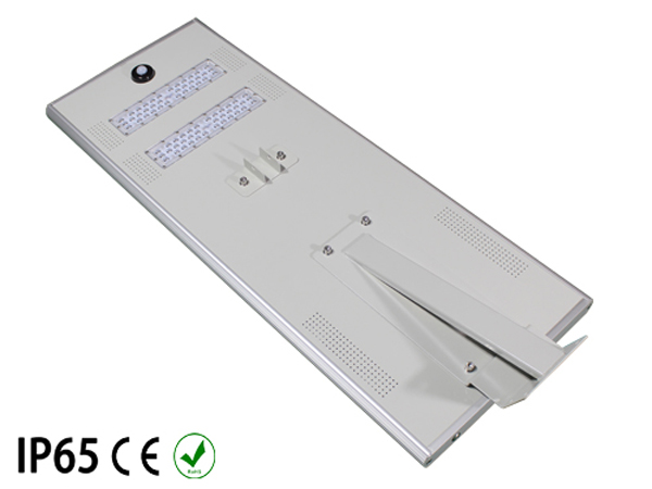
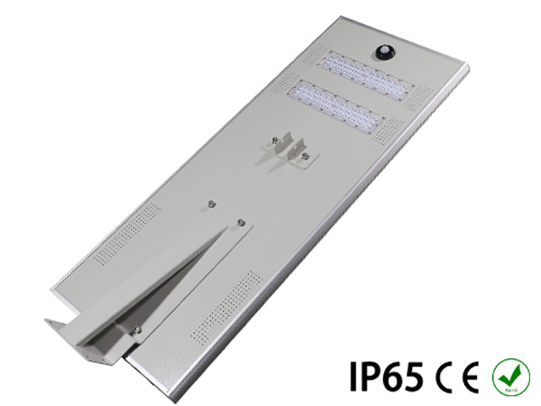
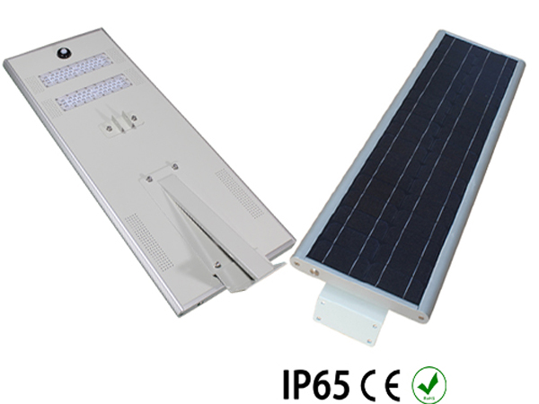
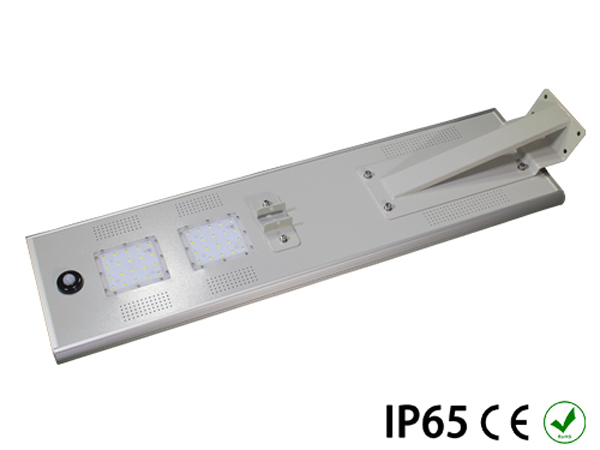
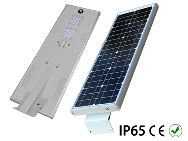
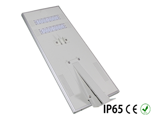
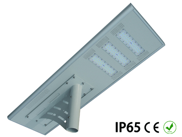
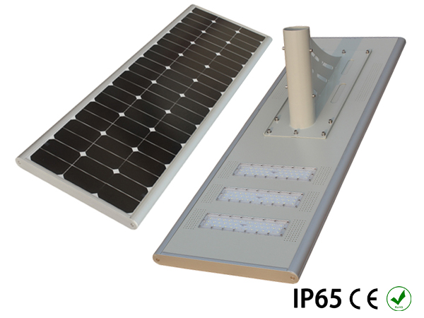
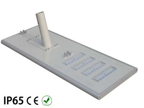
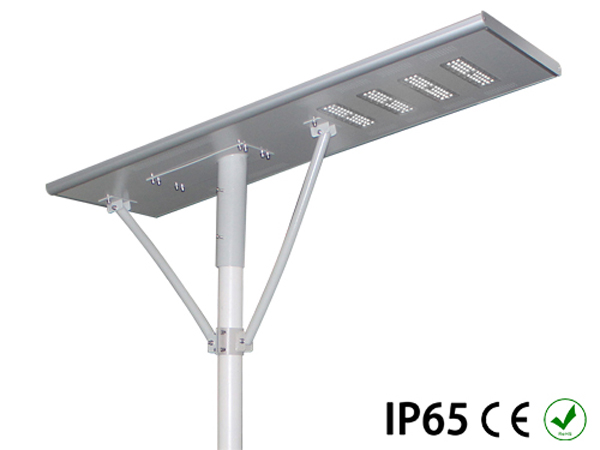
The all-in-one solar light is an integrated solar product with a sleek design that combines today's best green energy technologies (solar power, semiconductor LED light source, and lithium iron phosphate battery). Equipped with a smart motion sensor system, it achieves low power consumption, extended runtime, high brightness, and long maintenance‑free service life. It is also very convenient for transportation and installation.
Application:
Designed for installation on various traffic roads, auxiliary roads, residential roads, courtyards, mining areas, locations with limited or no grid access, parks, parking lots, and other outdoor spaces to provide reliable nighttime illumination. The solar panel charges the battery to ensure consistent lighting performance.
Product Composition:
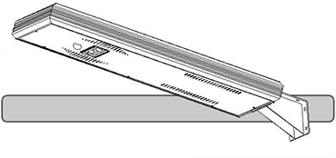
Composed of an integrated light unit (built‑in: high‑efficiency PV module, large‑capacity lithium battery, microcomputer MPPT smart controller, high‑brightness LED light source) and a pole.
Working Principle:
During the day, the solar panel generates electricity under sunlight. Through the control function, the solar panel charges the battery. At night, it automatically turns on the LED light (with motion sensor mode to reduce power consumption), illuminating the road through the LED light.
IMPORTANT SAFEGUARDS
When using electrical equipment, basic safety precau ons should
always be followed including the following:
READ AND FOLLOW ALL SAFETY INSTRUCTIONS
1. This product is used in areas with no electrical supply and/or
areas with good climatology. Can be used in a wide range of
places, such as roads, walking paths, parking lots, gardens,
residen al districts, etc.
2. When installing, be sure that the light can perfectly reach to the
panel light and is not blocked by any element such as buildings or
trees.
3. To avoid the possibility of electrical shock, turn o power supply
before install or during maintenance. It must be performed by
qualified personnel.
4. Product must be installed in accordance with your local electrical
code. If you are not familiar with these codes and requirements,
consult a qualified electrician.
5. Do not change the structure or any commponents of the
fixture
to ensure safety.
|
Model No.
|
Power
|
Dimensions
|
Weight
|
|
WS-LED-10
|
10W
|
502*295*65MM
|
5.3kg
|
|
WS-LED-15
|
15W
|
704*295*145mm
|
7.5kg
|
|
WS-LED-20-25
|
20W/25w
|
886*295*145mm
|
10.2kg
|
|
WS-LED-30-40
|
30W/40w
|
1114*295*145mm
|
15kg
|
|
SF-LED-50
|
50W
|
1114*420*145mm
|
18kg
|
|
SF-LED-60
|
60W
|
1114*420*145mm
|
19kg
|
SAVE THIS INSTRUCTIONS FOR FUTURE
REFERENCE INSTALLATION:
STANDARD MOUNTING
(Can be used in 10W/15W/20W)
STEP 1:
socket As shown in Diagram2, connect
the screw (M8*50MM) with nut (M8)
throughthe staple bolt, do not ghten.
STEP 2:
pole As shown in Diagram3, set the lamp
into the nut*¹ screw*² *¹ Nut: M8*² Screw:
M8x50mm body 2 light pole.
STEP 3:
As shown in Diagram4, adjust the body
to the appropriate loca on using No.14
wrench and 6mm Allen wrench with the
torque of body 15NM, then ghten the
crews.
STEP 4:
As shown in Diagram 5, installa on is
completed.
This marking indicates that this product should not be disposed with other household wastes throughout the EU.
To prevent possible harm to the environment or human health from uncontrolled waste disposal, recycle it
responsibly to promote the sustainable reuse of material resources. To return your used device, please use
the return and collec on systems or contact the retailer where the product was purchased. They
can take this product for environmental safe recycling.
STEP 1:
As shown in Diagram6, a er the lamp is
installed on the pole (installa on way
referred to the procedure used in 10w/
15w/20w),
connect the screw (M8*50MM)
with nut (M8)
through brace strut and
fastenings, do not
ghten; connect the
screw (M8*50MM)
with nut (M8) through
suppor ng hoop
component and brace
strut, do not ghten.
STEP 2:
As shown in Diagram7, connect the
screw
(M8*50MM) with nut(M8) through
brace
strut and suppor ng hoop
component, do
not ghten
STEP 3:
As shown in Diagram8, ghten the
screws using No.14 wrench and 6mm
Allen
wrench with the torque of 15NM.
STEP 4:
As shown in Diagram9, installa
on is
completed.
|
 Chinese
 English



 Wise Lighting Hotline
+86 130 5853 2903
Wise Lighting Hotline
+86 130 5853 2903